Diary of a dissatisfied customer
 
< Return to Problem page                
 

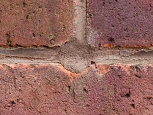
The Process (Assessment and Preparation Theory)

It needs to be remembered that the internal condition of cavities is beyond the control of the product manufacturer and the installer. However it is assumed that certification takes into account minor issues like excess mortar squeezed out of joints but not too much. In my case there is no evidence of mortar clumps or other blockages, where the void exists. The cavity there looks clean, hence my concern.

This page will lean heavily on the British Board of Agrément (BBA) document referred to previously and supplied by British Gas. Having examined this BBA document I can understand why the BBA refused to pass on the information to me because to anyone technically competent, the document is clearly flawed. It contains much that is good but it is still flawed when it need not be. All the fancy talk is not worth anything if it is not or cannot be translated into an ethical outcome. Text quoted from that document will be shown here grey.

1.3 The target mean density for the product, when installed, is 20 kgm–3. Local areas within the wall, when sampled over an area of 0.5 m2, may have a density variation of ±5 kgm–3.

That is very specific and obviously where any voids exist, that is not complied with. Evidence will be produced elsewhere to show that excess density can cause problems but that is not a concern at the moment though it might become a concern at remedial stage unless the cavities are subsequently emptied.

The product is delivered to site in polythene-wrapped bales weighing approximately 15 kg and should not be opened until required for use. The bags are marked with the BBA identification mark incorporating the number of this Certificate.

Someone has suggested that bales of insulation have been known to contain clumps of bonded fibres which can affect the injection process. If true that could be due to careless storage or damaged bales. The manufacturer may have processes in place to prevent such problems. All hearsay but it is something we need to be mindful of. The blowing machine may contain apparatus to break up any clumps before being discharged.

Care should be taken at this stage by the assessor and the party commissioning the work, to identify and agree in writing as appropriate, any areas of the wall that will not be filled (see section 16.6) and any special requirements for making good (see section 16.5).

12.2 Essential ventilation openings, such as those providing combustion air or underfloor ventilation, and all flues in the cavity wall must be checked. If adequate sleeving or other cavity closures are not present, installation must not proceed until these openings have been sleeved or otherwise modified to prevent blockage by the insulant.


The image on the left at A shows a ducted air-brick which is of course mandatory on new build where air-bricks are provided. B depicts the cavity tray which is also mandatory on new build but not practical retrospectively. My air-bricks are not ducted as is the case with all older homes. My air-bricks are for sub-floor ventilation only, not air-for-combustion. Some homes nearby may still rely on sub-floor air-for-combustion where they still support the underfloor-draught solid-fuel fires originally fitted to these homes.

In my case I have a meter cupboard (not sleeved) set in the cavity wall. I warned the installation surveyor about this for Health and Safety of personnel as the main electrical intake rises inside the cavity wall (drilling risk) and can be seen inside and outside with negligible excavation. Trace evidence of insulation can be seen inside the meter cupboard.

 
12.3 All uncapped cavity walls should be sealed prior to installation.

My home is 60's built and does not have the cavity closed at the top of the wall. Closing the cavity as depicted by A opposite is for all practical purposes impossible on an existing home. Standard practice on new homes we know but the BBA should acknowledge this point and prescribe accordingly. As it happens I am changing my roof coverings this year and can close the head of the cavity at the same time. That said I saw inconsistent evidence of insulation when renewing the soffits and facias in 2012 but further checks will now be employed.


These two images are taken from the BBA document and offer comprehensive instructions on the drilling pattern. Those images are backed-up by detailed written instructions.

Lay people should understand that the holes are 24mm diameter using an industrial hammer drill. That is a hefty piece of apparatus and given the mortar condition of most older properties, drilling too near the top of a wall or an opening, could result in brickwork being shifted or completely lifted off a joint. That is the reason also that holes are drilled at brick joints. What I call a Tri-Joint as seen below left.


16.1 Holes of 24 mm diameter are drilled in a square pattern at approximately 1.5 m centres. The topmost injection holes should be between 400 mm and 500 mm below the top of the cavity and no more than 1.2 m apart. The bottom row of holes should start between 0.5 m and 1 m above the dpc level while the holes nearest the corners of the building should be no more than 750 mm from the corner. Additional holes may be required to ensure complete filling round building features, eg under window sills, around air bricks, in column areas between doors and windows, at the tops of walls, and under gables. Holes under the windows should be drilled between 400 mm and 500 mm below the sill and no more than 900 mm apart. The topmost holes in the gable end should be no more than 1.2 m apart and between 400 mm and 500 mm from the verge (See Figures 1 and 2).

Obviously a thorough description and note the mention that additional holes may be required. However drilling too close to a window cill would almost certainly disturb brick joints unless a time-consuming 28mm diamond cutter was used. The latter is never used with a hammer drill.

 
16.4 The material is injected through a directional nozzle. Filling proceeds from the bottom to the top of the walls and from one end of an elevation to the other.

The sketch opposite shows a Directional Nozzle and is my own sketch. They are available in different lengths and diameters. The end at A is solid so that it hits the inner leaf of a cavity wall and then stops. The insulation arrives from the blowing hose in the direction of the arrow.

It can clearly be seen that as the name suggests, insulation emerges from one direction of the nozzle.

To see a proprietary nozzle run your mouse over the image on the right.


If we use the BBA sketch above and mark one injection hole red as shown on the left, it is self evident that to enable cavity fill to reach upwards to the whole of the area (400mm deep or 16 inches) under the window concerned, one of two truths need to apply. Either:
  1. The directional nozzle must be turned at intervals
  2. The pressure from the directional nozzle must routinely be such as to overcome the inevitable resistance to the flow of insulation trying to rise upwards towards the cill.

The BBA document makes no mention on this subject and in my view it should. Whether one or two applies it is self-evident that the directional nozzle should be inserted in a particular way each time it is inserted. We all need answers (in writing) to this specific question. It is of huge significance in this matter. If people will not answer questions in writing then assume they are wafflers and cannot be trusted until proved otherwise.

 
In the early days when I was getting no answers from Hillserve and British Gas I inevitably started to research the subject as anyone might do, technically qualified or not. It was not long before I discovered an excellent document by the well known Kingspan. I need say no more than invite you to read the document yourself. That helped inspire me to explore further and helped me realise this is not a one-off phenomenon.

My sketch on the right attempts to indicate the flow of insulation from the directional nozzle which is not strictly semi-circular as shown. A double curve is involved and insulation will spread sideways as well as downwards. The pressure downwards and sideways must inevitably, depending on the pressure, force insulation upwards as indicated by the arrows.

That will also have the effect of compacting the insulation at A but the insulation existing at A should in theory be the least dense as it is at the highest point of the layer below. We need to remember that there is a maximum density not to be exceeded.


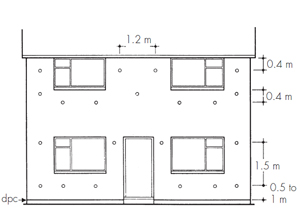
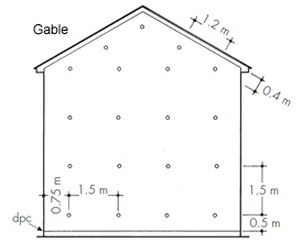
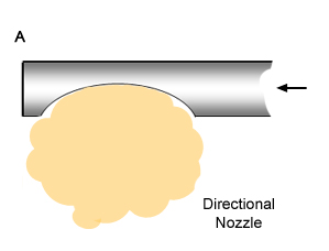
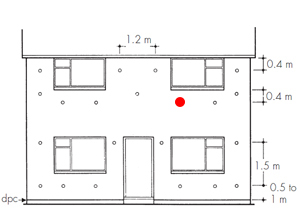
Presumably that is the reason for the protocol of starting from the bottom upwards after all drilling has been completed. It is also assumed that the height between injection holes is calculated accordingly. Nevertheless I still consider the use of the directional nozzle to be critical. Should the outlet of the directional nozzle always face downwards ? We are not told and in my view documents should be sufficiently complete as to enable an independent competent person to audit work carried out.

Obviously there is some speculation above. However as the BBA document does not mention how the directional nozzle has to be used, we must assume for now that it does not matter how it is used. The worst-scenario on the BBA sketch drilling pattern is shown on the gable elevation above where the injection holes are spaced no more than 1.500 metres horizontally and vertically.

We must assume that the position of the aperture in the directional nozzle is of no consequence and that the pressure and flow-rate of the filling material is such that it will fill the cavity however it is used with filling holes at the maximum centres stated.

For the benefit of lay people who have not witnessed cavity wall insulation being installed, the filling hose reacts to back-pressure and switches off the machine automatically once a particular void is filled. Whether or not the machine pressure is adjustable I do not know.

We have to accept that in the case of a severe blockage of mortar and/or brick debris in a cavity, back pressure resulting from the blockage can cause an injection machine to switch off without some of the area around a blockage being filled. Such blockages may arise from situations where holes are punched through walls for boiler flues, waste pipes or other purposes. Responsible contractors will use diamond cutters now which avoids the risk of blockages.

All that said, any system should be capable of working around reasonably expected issues like slightly squeezed mortar joints and fairly clean wall-ties.

The wholly independant and impartial Energy Saving Trust produce a useful document Cavity wall insulation in existing dwellings: A guide for specifiers and advisors which you may wish to read on the overall subject and different products. Under the Blown Mineral Wool heading there is a paragraph which is not seen in the BBA document:

If the filling time is less than normal, the cavity may not be full. The nozzle should be removed and the filling procedure repeated. If the filling time seems very much longer, work should stop and further assessment be carried out.

When you see the speed at which the work is carried out you will realise there is no time for niceties. What is known in the trade as bang, thump, wallop and out.

 
< Return to Problem page
Top of Page